|
Part 1: The termination |
(click photos for larger image) |
-
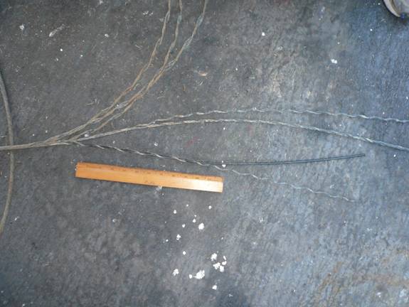
Inspect the conductive wire on the winch drum and cut off any severely rusty or kinked wire. Inspect a few wire strands & bend them back, if brittle, remove additional wire till you find pliable strands.
-
Pull at least 3m (~10ft) of winch wire on deck to allow termination on the wet lab bench top, if available.
|
-
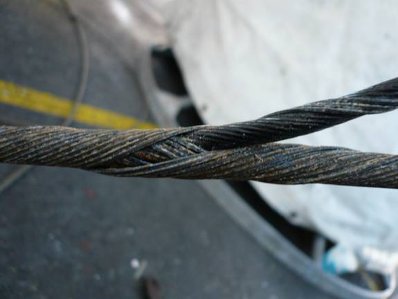
Unwrap the outer sheath ~2 m (6ft) length in 2 or 3 groups - keep them organized so rewrapping can be done easily.
-
Unwrap the inner sheath in 2 groups, exposing the conductive wire core then unravel 3 adjacent inner shield strands to keep with the core and use as ground.
-
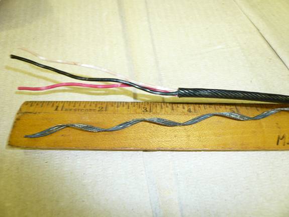
Trim the plastic core & 3-strands of inner shield to ~50cm (20") from the unwrap point. This will be long enough to terminate & reterminate at least once. Retermination will be required if a solder connection fails or from seawater intrusion.
|
|
-
Rewrap the unravelled shield back into a single, coreless wire, leaving the conductive core & 3 strands exposed. Tape the frayed end of the wire with black electrical tape.
|
 |
-
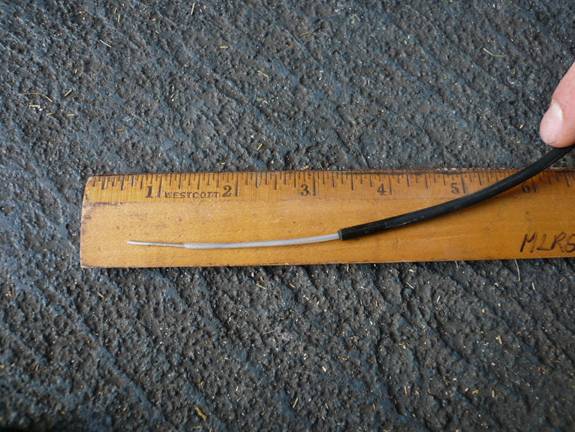
Strip ~8cm (~3") of the black, outer protective core. This is difficult & best done in small, 0.75cm (3/8") increments using coax cable stripper adjusted to cut the outer cover without cutting into the inner conductive wires. Careful when persuading off the black plastic covering you do not damage the conductive wires. Heat may be applied to the plastic covering to soften it, making it more malleable.
-
Strip ~2.5cm (1") from the ends of the three sea cable conductors, exposing copper wire ends.
|
 |
-
After stripping the 3 wire ends, exposing copper, conduct a 9-volt battery test if wire conductive integrity is unknown:
-
Inside the ship, at the CTD sea cable junction box, free the ends of all conductive wires from the wire poles.
-
Attach a 9 volt battery to two conductive wires at the termination end. Note the color & polarity of the wires and, moving back to the junction box, identify the two wires which read ~+9 volts on a multimeter. Record their color & polarity then switch the + battery connection to the other conductor & indentify its corresponding wire at the junction box.
-
The voltage readings will verify you have good conductivity - check for 'cross-talk' by measuring all the wires for voltage leakage. If any wire does not conduct the proper voltage or has a stable voltage reading when it is not connected to the battery, further testing is required to determine if that wire should be excluded from the termination.
-
Repeat, if necessary, until you've color keyed the three conductive wires and shield. Hopefully, the wire colors in the junction box agree with the conductive cable.
-
Connect the conductive wires to the wire poles in the junction box, noting the colors.
|
-
Strip ~2.5cm (1") off four single-pin Impulse connectors; the forth one is for the shield. Our CTD pigtail has single-pin male connectors so single-pin female connectors are solder to the sea cable conductors.
-
Use 95% alcohol on a large Kim-wipe to de-grease all the wire surfaces for good adhesion of shrink-tubing, tape, electrical putty & coating. Let dry a few minutes.
-
Be sure to slip on the Impulse connector sleeves before soldering & color code them with tape to match the junction box wires. Use the wire color key from step 10 to coordinate the connector color to the proper junction box wire.
|
|
-
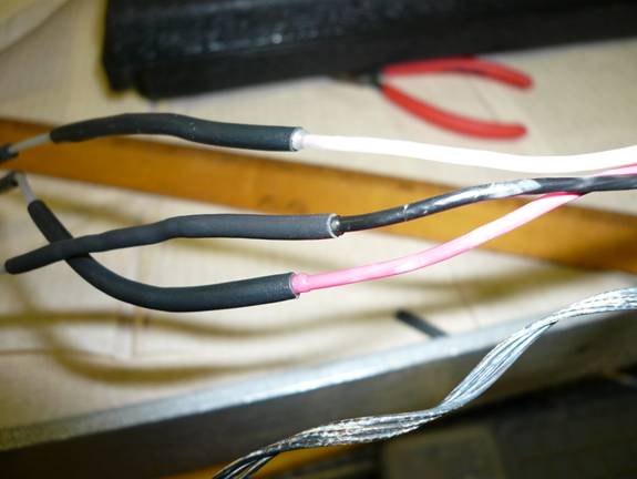
Slip adhesive-lined shrink tubing, trimmed ~1cm (0.5") shorter than the bare wire, up the wire away from the end to be soldered. Solder wires, paying particular attention to not melt shrink tube prematurely.
-
If there are any sharp wire ends protuding from the solder weld, file them smooth.
-
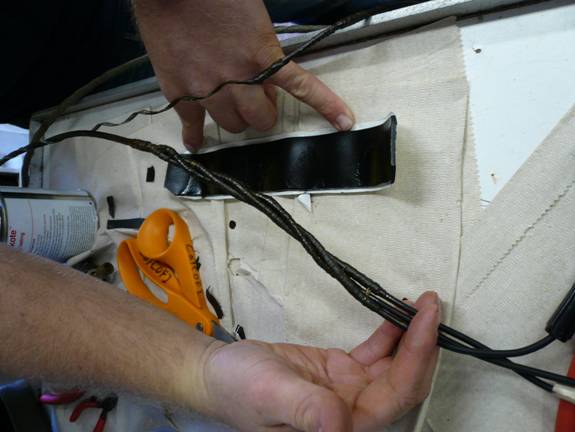
Let the solder weld cool for ~30 seconds then slid the shrink tubing evenly over the weld. Apply heat, starting from the middle and working toward each end, until all air is expelled. Adhesive should seep from both ends of the shrink tubing insuring a good moisture barrier (see photo).
-
For the shield-ground connection, snip off one shield strand then use an emory cloth to remove oxidation & rust from the ends (~4cm) of the remaining two stands. Using a crimp connector, crimp the Impulse connector wire to the two shield strands then fill the crimp with solder. Shrink tubing does not need to be applied to this connection.
|
 |
-
Smoothly (no bubbles) apply Scotch-Coat electrical coating to each wire individually. Scotch-coat ~7cm (3") up onto the black core & Impulse connector insulation. Keep all wire separated as they dry 20-30mins.
-
Split 1.9cm (3/4") insulating tape in half with sharp scissors so you have a 0.95cm (3/8") wide piece about 16cm (6") long. Starting ~2.5cm (1") up on the Impulse connector's black insulation, tightly wrap the wire with insulating tape sticky side up. Wrap your way down onto the thinner wire using multiple layers of insulation tape to reinforce and strengthen the thin diameter junction. Stretch and tightly wrap your way up to the black plastic core, stopping where the three conductors come together. Repeat for the two other conductors.
-
For the shield connector, start wrapping 2.5cm up on the Impulse connector's black insulation. Tightly wrap the wire to prevent moisture intrusion under the connector insulation then continue up & over the crimped connector.
-
Apply Scotch-coat to all the individual wires once more and let dry 20-30 minutes.
-
(Optional) Repeat step 18, adding a second layer of insulating tape onto the three main conductive wires. On the third wire, instead of stopping where the three wires meet, continue ~6cm (2.5") up onto the black plastic core with the final wrap
-
Apply Scotch-coat to the four wires and let dry.
|
-
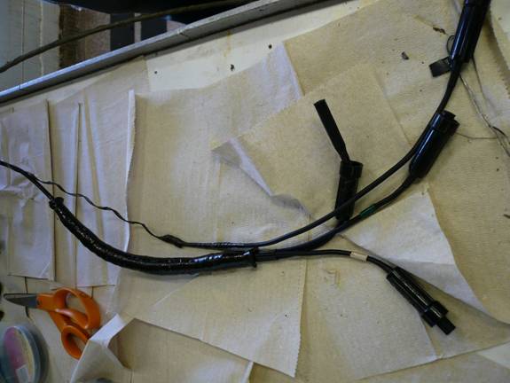
Cut a piece of electrical putty tape slightly longer then length of the termination, trim off the four corners and wrap it around all wires like a taco, not however, before twisting all wires together to form a spiral braid. Pinch the putty edges together forming a seamless tube around the termination. Squeeze the putty into the air pockets between the wires - try to eliminate as much trapped air as possible by kneading outward from the middle.
-
Wrap the putty 'tube' with Super 33 electrical tape, starting at the middle and working toward the loose end, wrapping very tightly. When you reach near the edge, leave 0.5cm of the putty unwrapped, then wrap back to the center normally (tight but not stretching the tape); once back to center, repeat the technique on the other half, wrapping tightly to near the edge then back to middle normally until you've completely double-wrapped the termination. It is important to leave each end open so as the putty compresses, it can seep out the ends.
|
|
-
Apply a final coat of Scotch-coat, sealing the tape surface.
-
Loosely wrap the ground wire to the outside of the termination then tape it in place so all connectors are gathered together.
|
 |
|
Part II: The Sea-cable Connection |
|
-
Using the cable color key from Part 1 step 10, at the junction box, combine two conductors for signal (usually red & white) then the third conductor to ground. Using the shield is standard practive but on some ships, it generates electrical noise (spikes).
-
At the CTD, plug in the appropriate connectors to the CTD pigtail - the signal and common (ground) pairs are indicated on the pigtail sleeves (engraved on our pigtail). There are four connectors on the CTD-pigtail but they combine into signal pair & common pair.
-
Turn on the deck unit, if everything is connected properly, the front LED panel should read something other than '0000000000'. If you get zeros, the most common problem is reversal of signal & common. See CTD Diagnostic web page for troubleshooting instructions.
|
|
Part III: The Rigging |
|
-
Disconnect the CTD pigtail from the sea-cable termination.
-
Lacing the wire down through the center of the rosette, loop the termination and sea-cable end once around the rosette frame and along side the CTD cage, paying careful attention to the placement and orientation of the termination. Adjust the length so the termination & pigtail are easily secured, protected, but accessible when cable harnesses are in place.
-
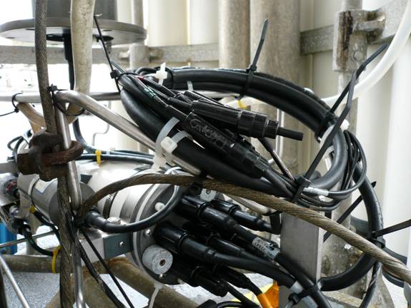
Use heavy duty cable-ties to secure the sea-cable to itself (loop) and to the frame until cable clamps can be tightened.
-
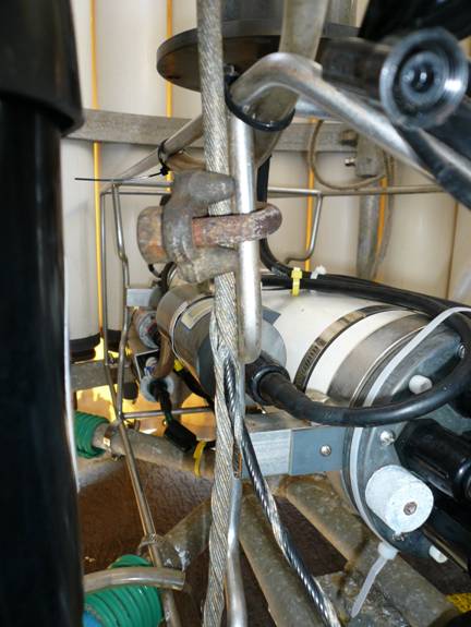
Place a large cable clamp on the wire and the fish cage (see photo). This cable clamp immobilizes the conductive wire so when the CTD-rosette is lifted, there is no tension on the termination. Tighten securely but do not over-tighten or you may interrupt the electrical continuity & create a short.
|
 |
-
Add two smaller cable clamps on the wire loop about 12cm (5") from the end of the loop and about 40cm (15") from the end of the loop. Note that the 40cm clamp is not visible in this photo. This is the main safety for the CTD-rosette should the the guy-wire grip ('Chinese fingers') fail. It is important to be sure the loop does not interfere with the bottle mounting or closure of the bottom lids.
-
SIO-CalCOFI prefers to rig this loop at the end of sea-cable as a safety line should the guy-wire grip slip or fail.
|
 |
-
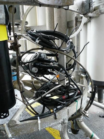
Cable-tie the sea-cable loop to the cage, making sure it does not rub against or interact with CTD sensor cables.
-
Loop the CTD pigtail and sensor cables on the upper or lower cage and secure with multiple cable-ties. It is important the cables not move during the cast especially during rough weather.
-
Double-check all wire & sensor connector sleeves are tight.
-
Make 'shallow' (1000m rated) sensor cables accessible so they can be easily disconnected & dummied when sensors are removed for 3500m casts.
|
 |
-
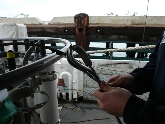
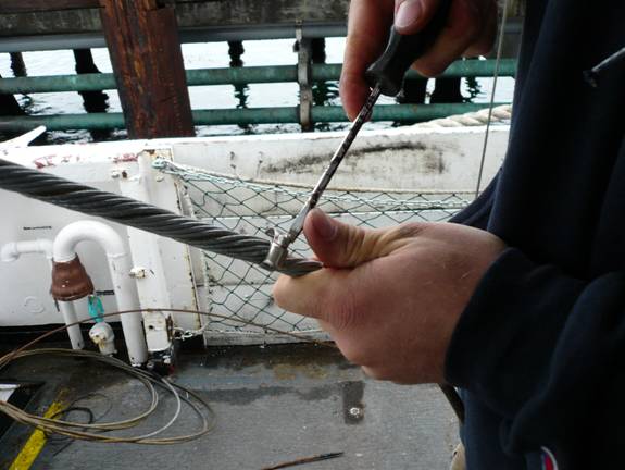
Shackle the sea-cable to rosette frame using a guy-wire grip (guy-cable grip, sometimes called "Chinese Fingers" after the kid's finger trap). Hold the sea-cable up vertically over the rosette center. Allow enough slack so when lifted by the wire grip, there is no tension between the shackle and the cable clamp attached to the CTD cage. This determines the wire grip attachment point up the wire - mark it with black tape. The sea-cable can then be lowered to chest-level for installation.
-
Secure the stainless thimble in the loop of the wire grip with black tape. Begin wrapping the guy-wire grip around the cable. Towards the end, it becomes increasingly difficult to seat the ends of the grip. You may have to use an broad blade screwdriver or tack puller tool to finish the job.
|
 |
-
Put a small hose clamp or sturdy cable tie at the top of the guy-wire grip to keep from the ends from unwrapping.
|
 |
-
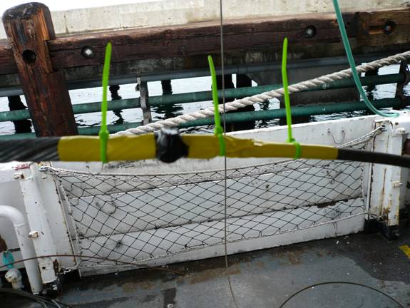
Wrap yellow tape & hi-vis zip ties around wire to help the winch operators' visual determination of optimal 'just below surface'.
-
If the CTD frame shackle has a cotter pin, pass the shackle bolt through the wire grip thimble so that cotter pin is opposite the wire bow. This helps prevent the CTD wire from being pinned under the shackle when slack is removed during deployment.
-
Using 'tuna-cord' or thin nylon line, tie the sea-cable slack out-of-the-way of the bottle lanyards.
|
 |
|
Tips & Reminders |
|
-
The conductive core has a clear tape length index. When unwrapping the core, save the length reading for the ship's cable log.
-
Wire colors can change from the sea-cable to the junction box because the sea-cable conductors are soldered to the junction box wires at the winch's slip rings. This termination can become faulty over the course of the cruise so when troubleshooting signal interruptions, take that into consideration.
-
The longer the length of exposed wire core you leave when unwrapping the shield, the more chances of reterminating without have to unwrap the shield. 50cm (~20") of exposed wire core is enough to reterminate at least once.
-
Cut 2 strands of inner shield approx the same length as the conductive core for ground crimp connection. If you want to use three shield strands, use a larger crimp - we use bare metal crimps that accomodate two shield strands and one Impulse wire.
-
Once the inner connectors are stripped to bare wire, wipe all surfaces of the wire with 95% ethanol to ensure a clean, grease-free connection.
-
Make sure the work space is fairly clean and the work surface is covered with paper towels to catch electrical coating drips.
-
Keep the electrical tapes clean of lint or other debris so wraps are bubble & lint free.
-
If the CTD wire becomes kinked or develop a mechanical weakness in the first several meters (between CTD & winch). It may be possible to continue to use the wire without re-terminating as long as signal continuity is intact. Move the guy-wire grip above the problem area and loop the extra wire along the upper rosette ring. Secure the looped wire with strong cable ties.
-
On ships with side-by-side CTD & Hydro winches: if the CTD conductive wire "jumps the shieve" it may be possible to use the hydro winch to lift the CTD-rosette (or any tethered instrument) and reseat the wire in the shieve. (Restech Bob Wilson 101)
-
Secure the CTD-rosette to the cleats using the taglines to minimize the chances of losing the package if the wire parts.
-
Attach a fresh guy-wire grip to the CTD wire reversed - thimble up, ends down.
-
Switch the hydraulics to the hydro winch.
-
Attach the hydro wire shackle to the guy-wire grip thimble and use the hydro winch to lift the CTD-rosette until there is enough slack to slip the wire back into the shieve.
-
Keep the CTD wire under tension so it stays in place as you carefully pay out wire on the hydro winch.
-
Once the CTD wire is holding the weight of the CTD-rosette, unshackle the hydro wire and remove the wire grip.
-
Return the CTD-rosette to deck and assess any damage to the conductive wire. Reterminate if the integrity of the wire is compromised.
|